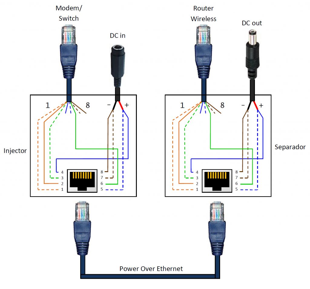
Poe Rj45 Pinout Diagram Wiring Diagram Poe Ip Camera Wiring Diagram
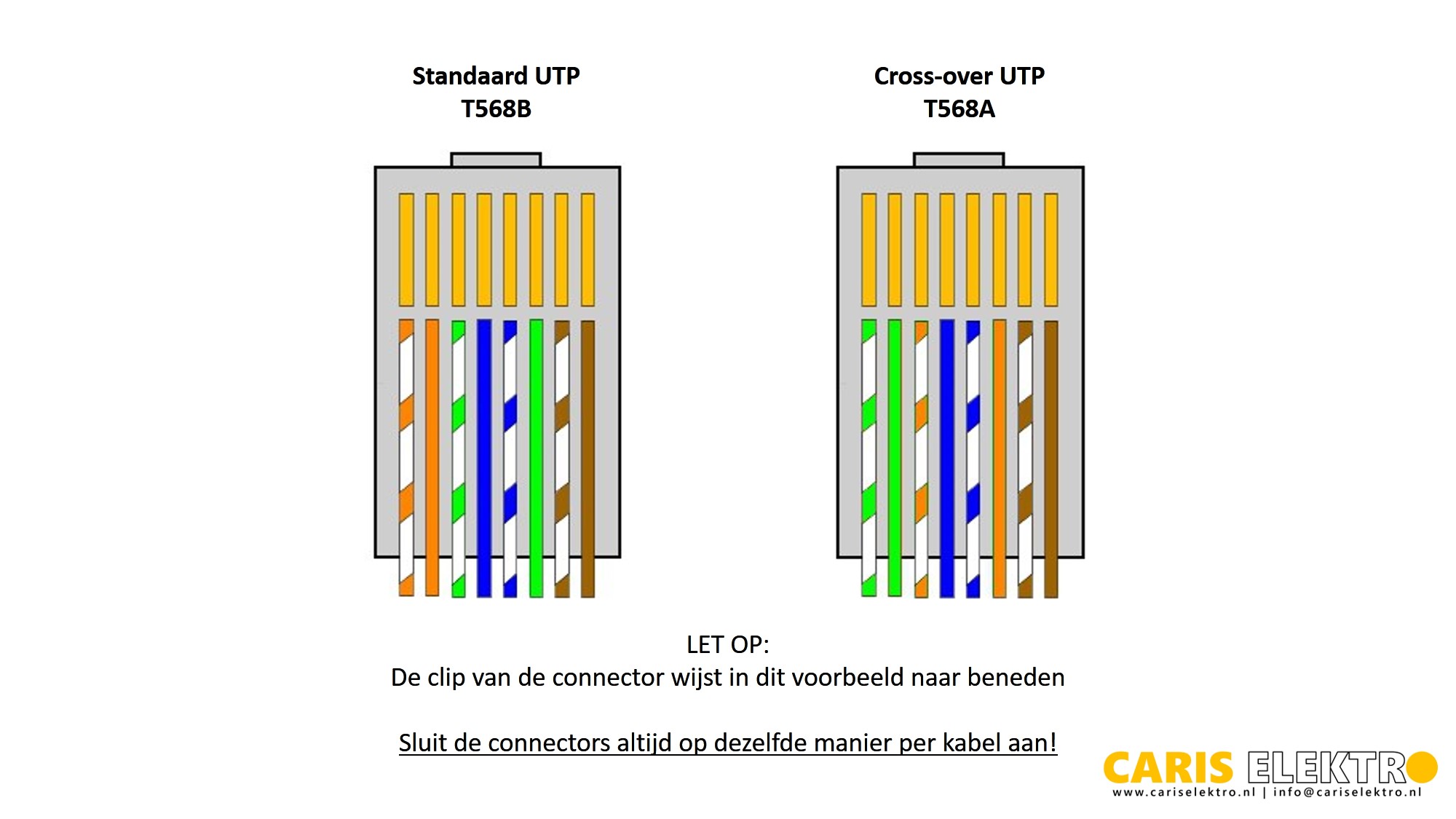
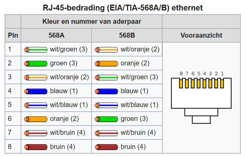
T568B is the standard followed by the majority of Ethernet installations in the United States for RJ45 color code. It is the more common standard used when cabling for businesses. T568A T568A is the majority standard followed in European and Pacific countries. It is also used in all United States government installations.

T568B Rj45 Jack Wiring Diagram Buy best boxermen shop
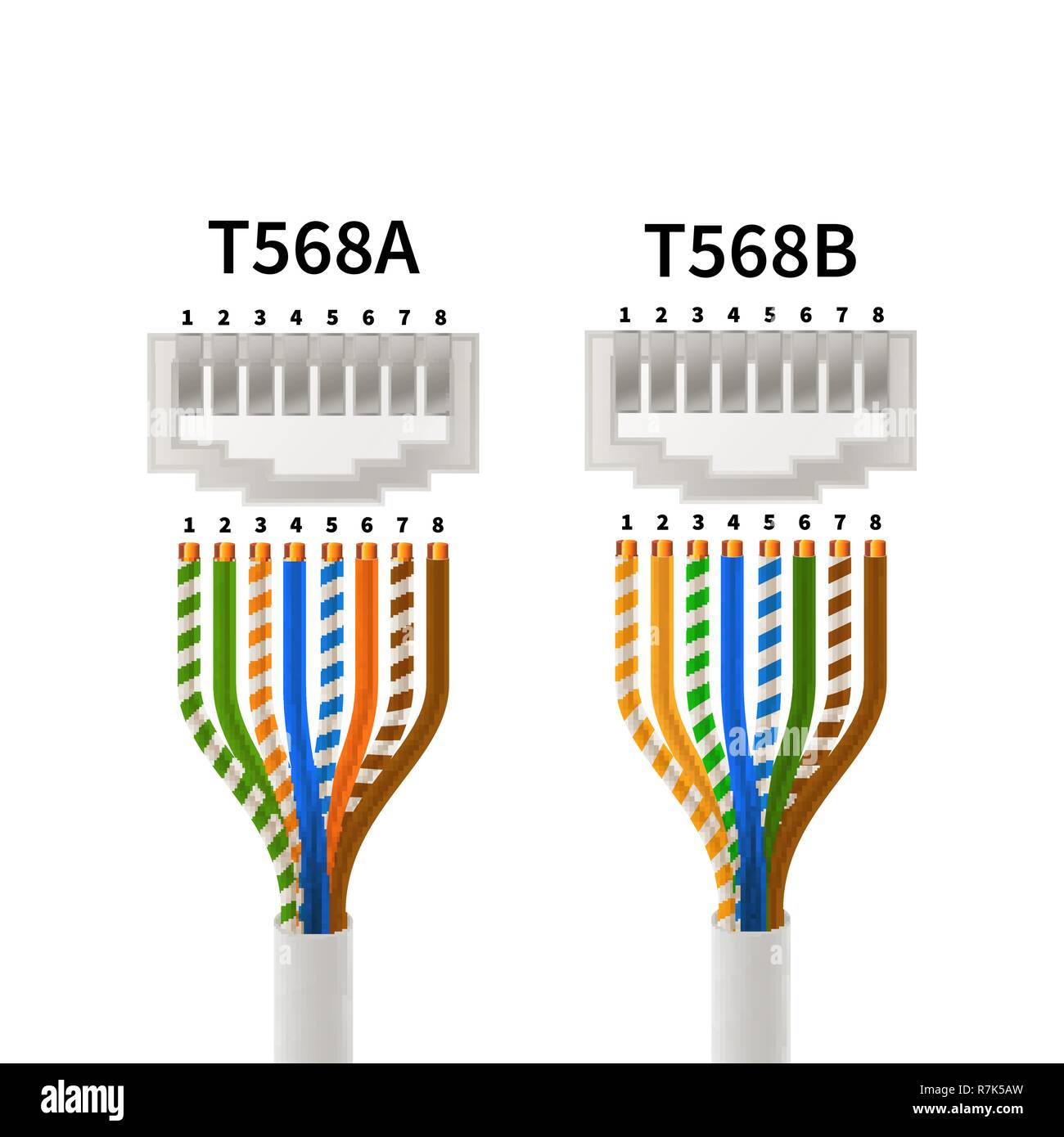
RJ45 Pinout Diagram. December 24, 2016 CCNA. RJ45 (Registered Jack 45) is the connector that consists of 8 metal connection point. RJ45 pinout diagram shows the way how that connector provides communication with network devices. RJ45 exists at the end of the ethernet cables that is used for internetwork communication. There are T568A and T568B.
Rj45 Aansluitschema
The ethernet cable used to wire a RJ45 connector of network interface card to a hub, switch or network outlet. The cable is called wipe, patch cord, straight-thru cable.

Branchement Prise Murale Rj45 DemaxDe
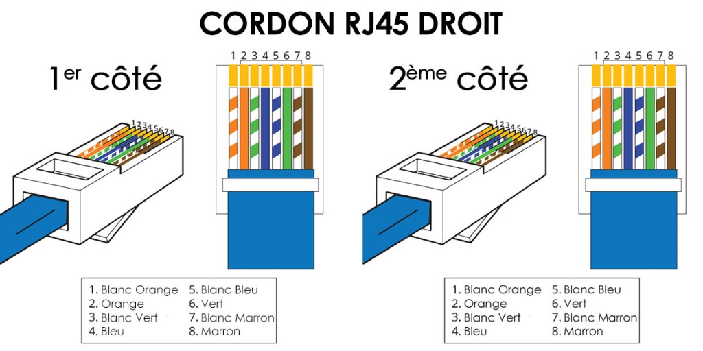
Pour réaliser le branchement prise RJ45, la toute première étape consiste à tirer le câble Ethernet depuis le tableau de communication jusqu'au niveau de la boîte d'encastrement où la prise RJ5 devra être installée. Ensuite, le câble devra être dénudé sur environ 5 cm afin de bien ressortir les brins.

schéma de branchement prise RJ45 téléphone câblage les différents
Find the deal you deserve on eBay. Discover discounts from sellers across the globe. No matter what you love, you'll find it here. Search Rj-45 ethernet cable and more.
Collegare lo schema elettrico Immagini senza sfondo e Foto Stock
This type of wiring uses the blue and brown pairs for transmitting data while the orange and green pairs are used for receiving data. This type of wiring is generally used in commercial applications, such as connecting a server to a router or modem.
[20+] Schema Prise Rj45 Male, PLATINUM TOOLS EZRJ45 CONNECTORS AND
By John Peter | April 7, 2023 0 Comment Understanding Rj45 Wire Diagrams: How to Safely Install Cables The RJ45 wire diagram is an essential tool when it comes to wiring any device using the RJ45 standard.
Rj45 Aansluitschema
Male RJ45 plugs separate and correctly terminate these eight individual wires. In other words, RJ45 wiring is based on an 8P8C (8 position, 8 contact) configuration. Standard RJ45 is defined as a mechanically-keyed variant on a generic 8P8C body. Mechanically keyed essentially means that RJ45 connectors also include an additional tab.

Schéma de cablage RJ45 Prise rj45, Réseau informatique, Installation
This RJ 45 pin diagram (T-568B) shows everything you need in one handy image, with iso-view and RJ45 color order, suitable for printing quite large. I like this pinout diagram because it shows everything you need. It includes an isometric view and pin-color order table, all in one large diagram.
2 different terminations? Networking Level1Techs Forums
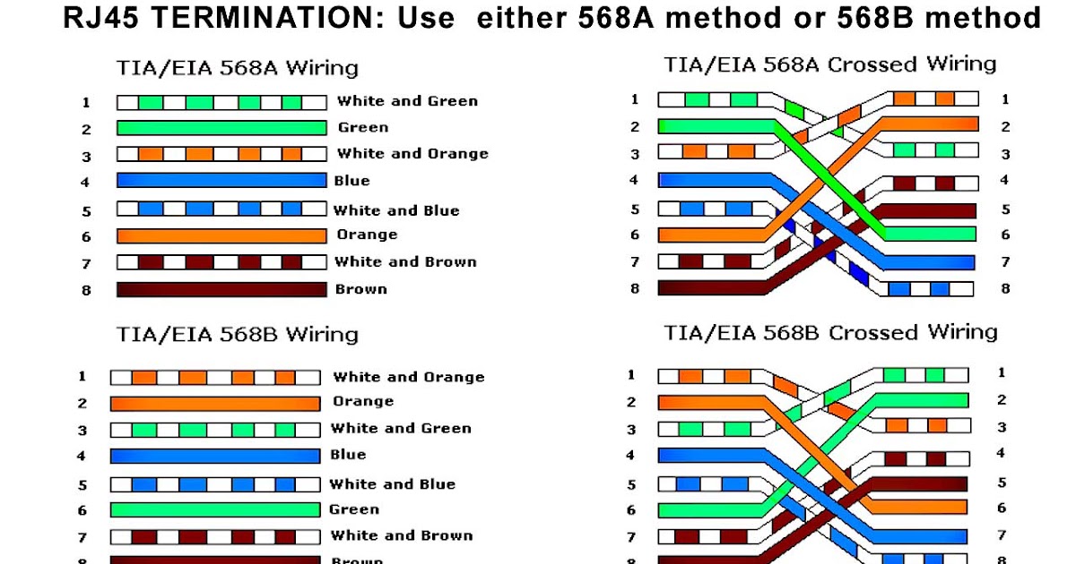
Wiring scheme B (or T568B) is used for RJ45 wiring and uses different wiring colours to scheme A (or T568A). If you compare the pin functions of both scheme A (T568A) and scheme B (T568B) you will find that they are the same, and only the wiring colours are different.
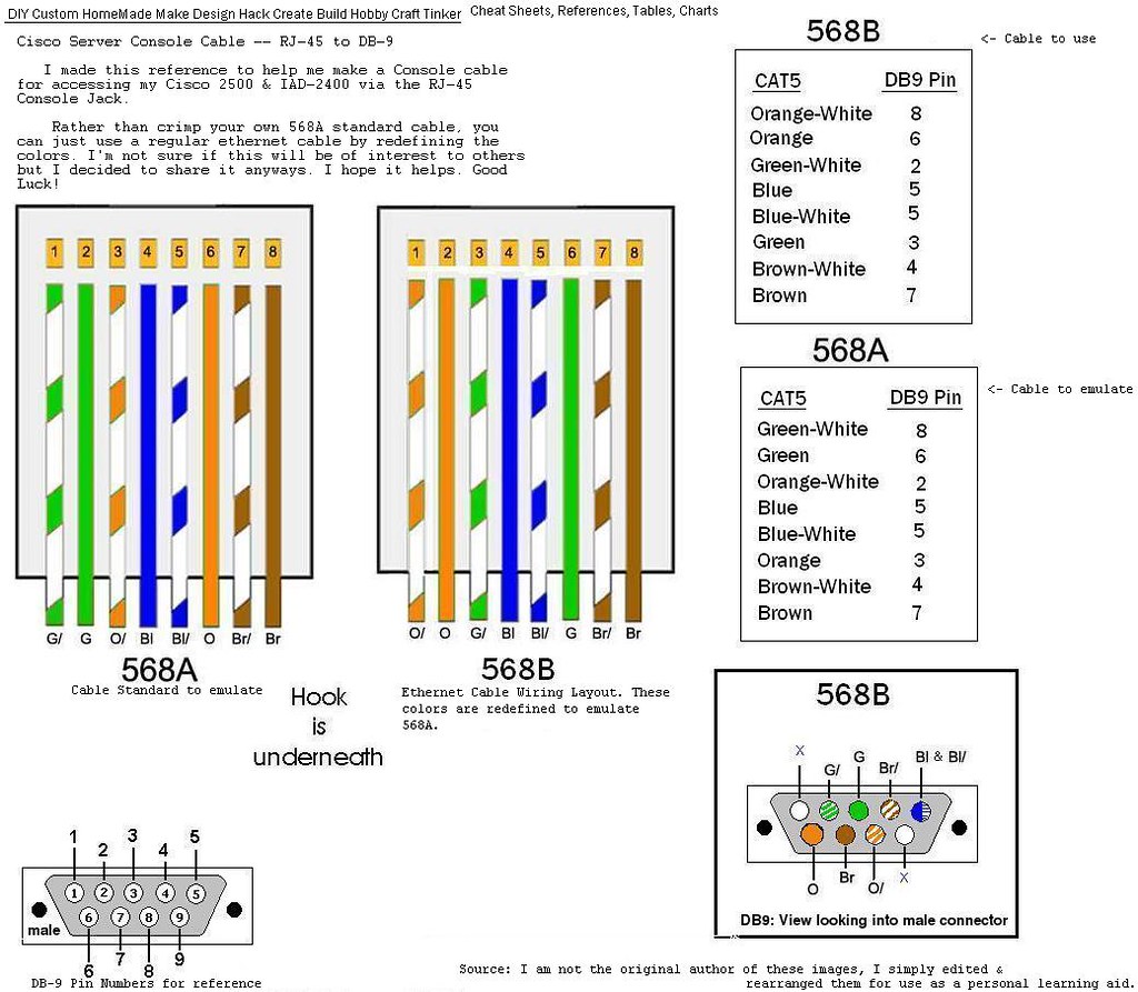
Custom_CiscoRJ45toDB9_ConsoleCable_WiringPinout Flickr
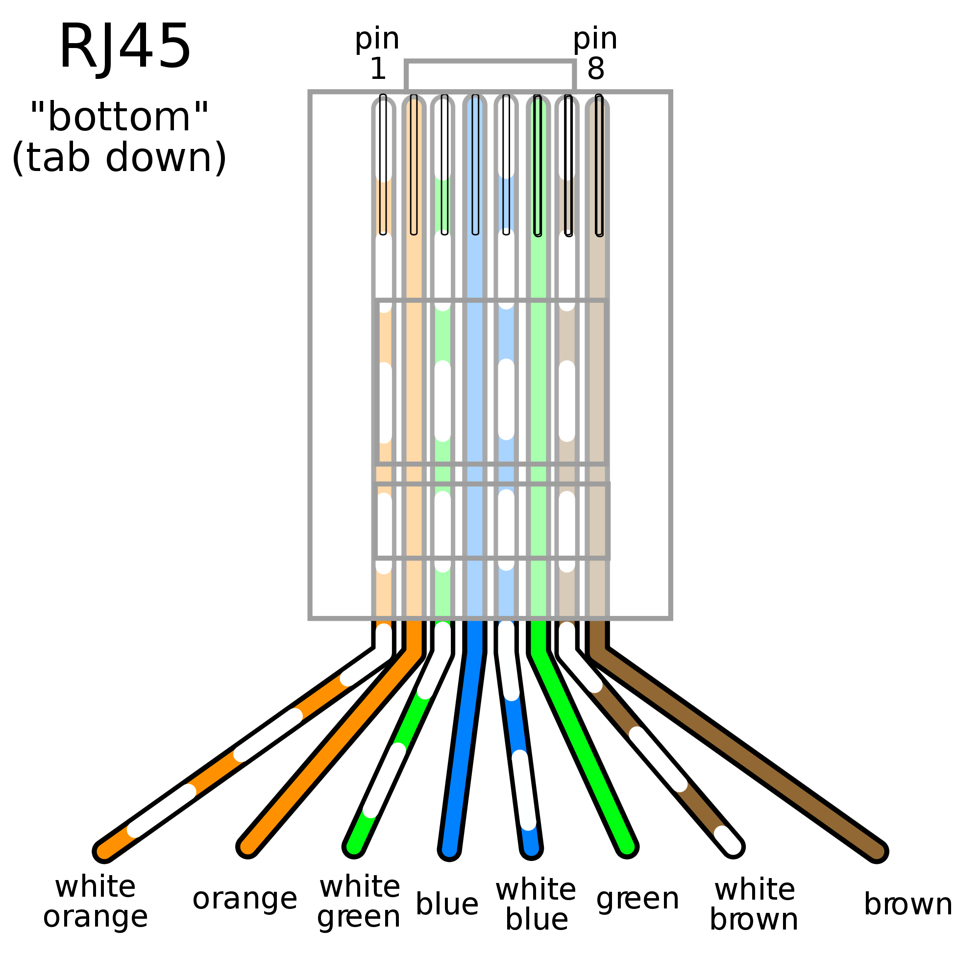
RJ-45 conductor data cable contains 4 pairs of wires each consists of a solid colored wire and a strip of the same color. There are two wiring standards for RJ-45 wiring: T-568A and T-568B. Although there are 4 pairs of wires, 10BaseT/100BaseT Ethernet uses only 2 pairs: Orange and Green.

Modemrouter Linkem vs switch DLink DES105 Hardware Upgrade Forum
But when it comes to choosing which type of RJ45 to use, one may come across the debate between using an RJ45 Schema Best A or B. RJ45 Schema Best A uses a T568A wiring configuration, which is suitable for connecting computers and other network devices over copper cabling. This wiring configuration is the most common for Ethernet.

Schémas électrique
Today my topic is about Ethernet RJ-45 connector pin assignment of both T568 A and T568 B. At the end of the video, l will provide one performance-based simu.
[27+] Schema Branchement Prise Rj45, Schema Branchement Cablage Pise
Scheme A and scheme B are for an 8-conductor cable consisting of four pairs, for RJ45 connectors. Wiring Diagram Colour Code The diagram above shows the Ethernet pinout for scheme A. In scheme A, pin 6 and pin 3 are assigned orange pairs, and pin 1 and pin 2 assigned green pairs. A or B

schéma de branchement prise RJ45 téléphone câblage les différents
T568A and T568B are the termination standards used by Internet backbone infrastructure, Internet providers and all the way down to homeowners or businesses. The only real difference between these two pin-to-pair assignments are the green and orange pairs. These two sets are swapped in the cable.
Cat 6 Wiring Order
RJ45 wiring is the technical term for wiring that consists of four twisted pairs of wires in an eight-pin modular connector. This connector is often used in Ethernet networks and is compatible with many varieties of LAN cables. An RJ45 connection allows for the transfer of data from one device to another across a digital connection.
