PCB Troubleshooting Tips & Techniques A Complete Guide
Apply heat: Add a very small amount of solder to the tip of the iron to help with heat conduction, then apply the tip of the iron so it touches the board and the component lead simultaneously. This applies heat to both parts and prepares them for soldering. Apply heat for a few moments before moving on to the next step.

Vokera PCB repair 20071334 Heating & Catering Parts
Are you looking for pcb repair techniques? Visit https://soldertraining.net/ipc-7711/21-pcb-rework-and-repair/. They are confident in their staff and their a.
Printed Circuit Board Repair Services Circuit Board Repair
Step 1 - Identify the Damaged Trace Step 2 - Clean the PCB Step 3 - Prepare the Copper Trace Step 4 - Apply Flux Step 5 - Solder the Trace Step 6 - Test for Continuity Frequently Asked Questions (FAQs) What causes PCB traces to get damaged? Can I repair a PCB trace without soldering?

PCB Repair Giz 10p
How to Repair Circuit Boards? July 13, 2023 PCB Techniques Will Li Will is proficient in electronic components, PCB production process and assembly technology, and has extensive experience in production supervision and quality control. On the premise of ensuring quality, Will provides customers with the most effective production solutions.
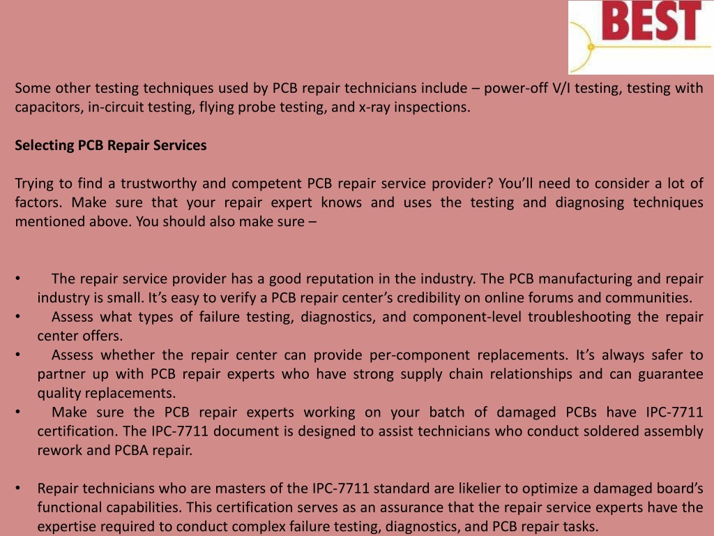
PPT PCB Testing and Diagnosing Techniques You Need to Know Before You Get Circuit Board PCB
Before applying the mixture of overcoat epoxy, you should clean the cracked area. Some plastic picks are practical to use the epoxy to the PCB crack. The pot life and the tack-free time need to be around 20 min and 30 min, respectively, at 25⁰C. You can cure the cracked circuit board at 100⁰C. For around 10 minutes.

EE人必練:PCB維修基本功法 電子技術設計
Step 1: Remove the damaged pad or component First, secure the PCB to your work surface so that it doesn't move around while you're working on it. It's best to use tape.

Why break a PCB trace plane into multiple parallel traces? Electrical Engineering Stack Exchange
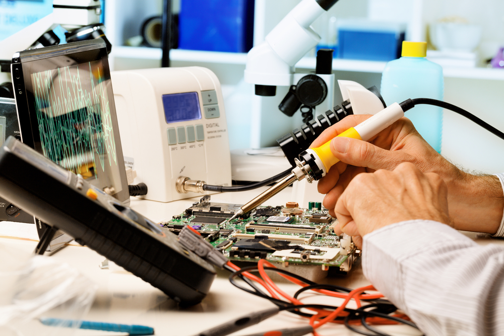
Rework is a repair technique that usually involves repairing a PCB that has surface mount components that are not working correctly. The process usually involves the use of special tools such as rework stations and specialized soldering irons. Rework is a complex process and usually requires an expert's help.
Rework and Modification of PCB Yun Industrial
The 5 Most Common Printed Circuit Board (PCB) Repairs - EMSG 5 Most Common PCB Repairs Many don't realize that the electronics, devices, and items they own are built upon several internal components which work collaboratively to provide the necessary functionality and features they use.
PCB Repair
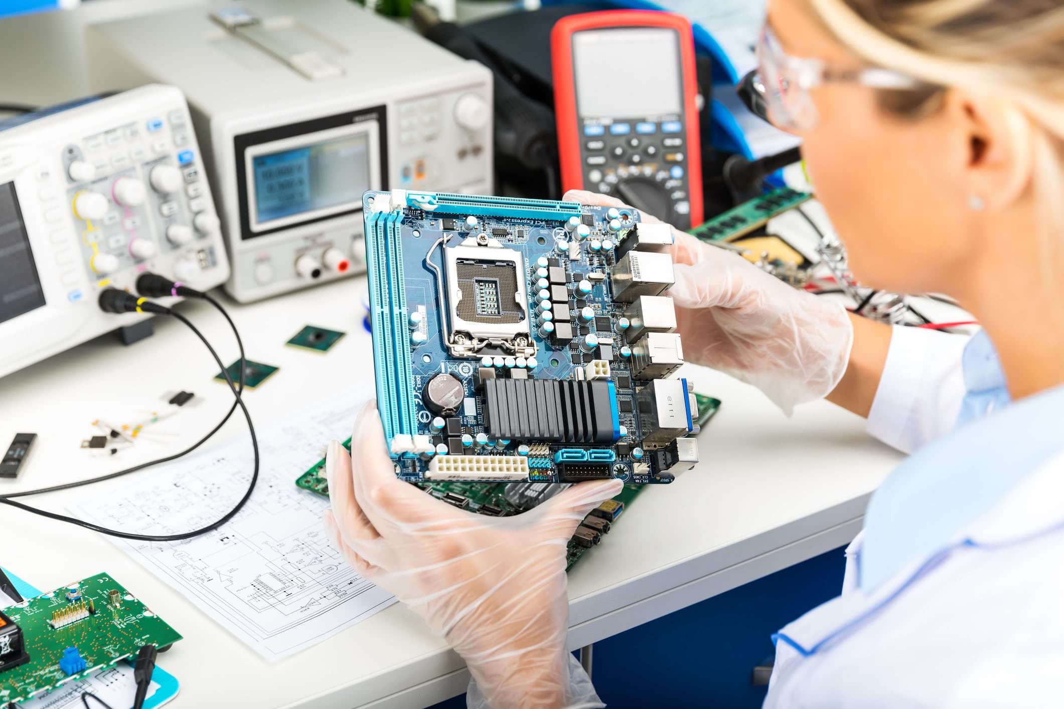
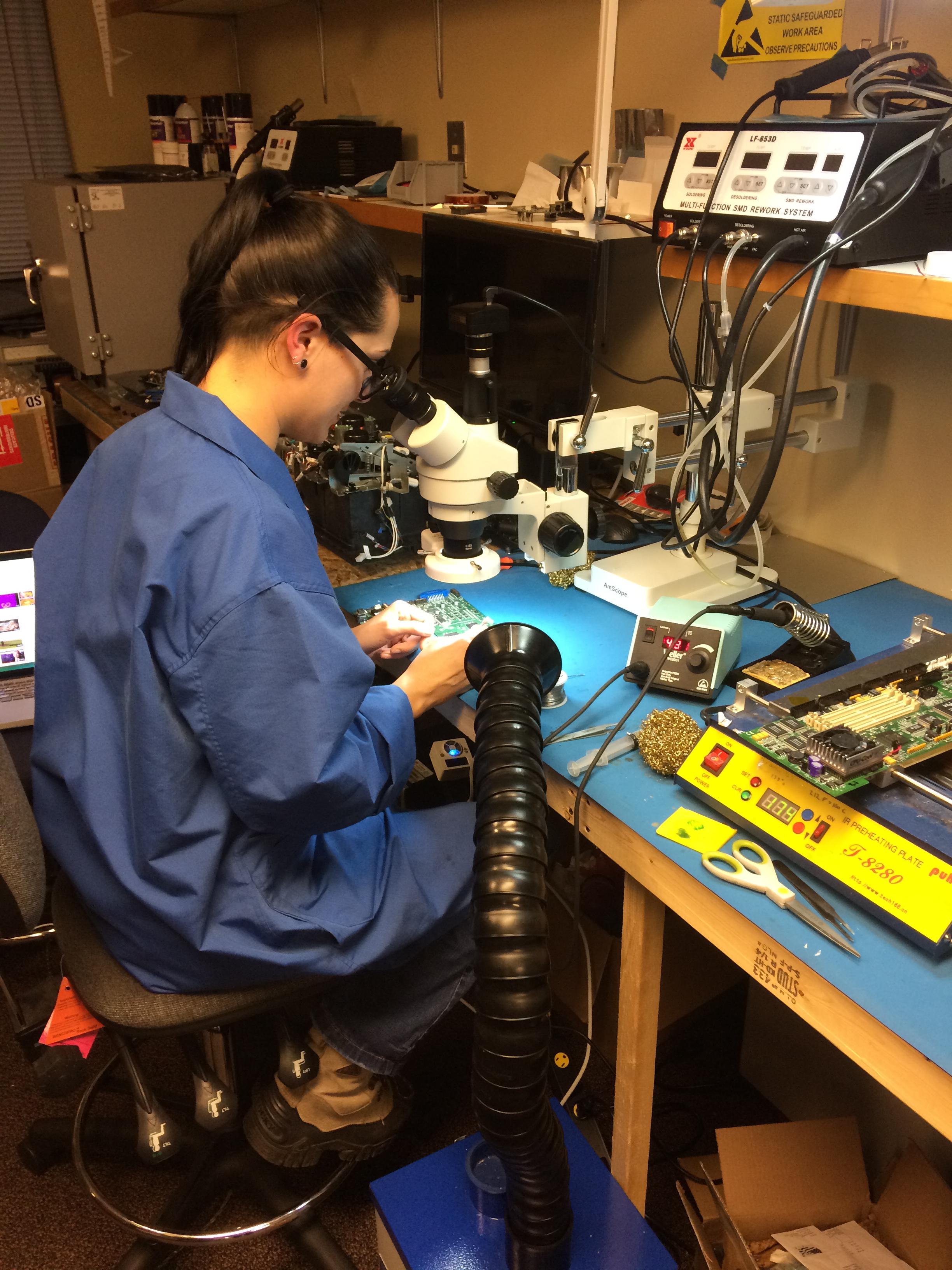
A typical technician working on a PCB can generate thousands of volts. SMOS logic devices can be damaged with 250-3000 volts, EPROM devices down to 100 volts, and microprocessor chips as low as 10 volts.

PCB Repair 6 Steps Instructables
Printed circuit board assembly (PCBA) is a cost-effective hardware device used in mechanical, process, electrical, electronic, military, and medical equipment providing automated and digital functionalities for users. Keeping high quality standards in the PCBA production process is a major challenge for the electronics production industry. Defective PCBAs are submitted to analysis, debug, and.
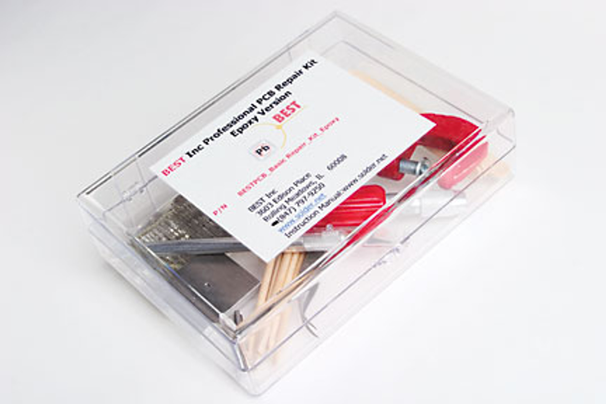
PCB Repair Kit for repairing most physical damage to a PCBepoxy version
PCB rework is the process of making changes to or fixing flaws on a printed circuit board after it has already been produced or assembled. This may require anything from changing components to cleaning up excess solder to fixing broken traces or pads.

Pcb repair Hobby electronic soldering and construction
4.2.2 Conductor Repair, Foil Jumper, Film Adhesive Method R, F, C High A C 4.2.3 Conductor Repair, Welding Method R, F, C High A C 4.2.4 Conductor Repair, Surface Wire Method R, F, C MediumI C 4.2.5 Conductor Repair, Through Board Wire Method R MediumA C 4.2.6 Conductor Repair, Inner Layer Method R, F High E D
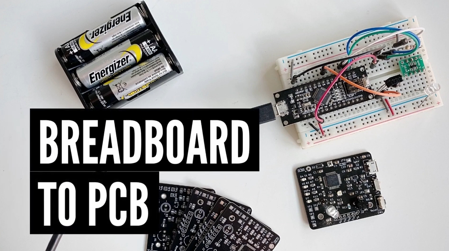
Design considerations for transferring a breadboard prototype to custom PCB
Discover the importance of professional PCB repair services in maintaining the longevity of electronic devices. Explore common PCB issues, the repair process, necessary tools, and the choice between repair and replacement. Learn how to select a reliable repair service and gain valuable DIY repair tips. Ensure the optimal functioning of your electronic devices with expert PCB repair.

PCB Maintenance and Repair PCB Breakdown Electronic Repair
Step 1: Measure the length and width of the trace, ensuring it matches the repair area. Step 2: Scrape off a bit of varnish from both ends of the wire. Step 3: Place a piece of high-temperature tape on your worktable to prevent damage during soldering. Then apply solder to the scraped areas, being mindful of the amount.

Best Practices for PCB Soldering Techniques VSE
PCB soldering refers to applying solder to printed circuit boards, one of the most common types of soldering. There are various PCB soldering processes, though most typically involve joining components to the PCB surface to create electrical connections. PCB soldering is a vital skill for anyone working with electrical circuits.

PCB Repair Training YouTube
1.Fix PCB to your work surface then remove the damaged parts. Sometimes, diagnosing a damaged PCB requires an oscilloscope to probe the signal strengths and waveforms at various points to test for continuity of the circuit across the board.
