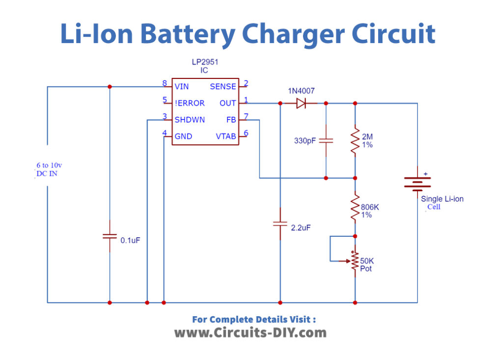
4 Simple LiIon Battery Charger Circuits Using LM317, NE555, LM324 Homemade Circuit Projects
Breakthrough Solid State Lithium Metal Battery Design Promises Rapid Charging and Longevity. Story by Ethan Brown • 3m. The race for the next big leap in battery technology may have found its.

pcb design LTC4002 LiIon Battery Charger... How do I connect the Comp pin? Electrical
4 Simple Li-Ion Battery Charger Circuits - Using LM317, NE555, LM324 Last Updated on January 2, 2024 by Swagatam 184 Comments The following post explains a four simple yet a safe way of charging a Li-ion battery using ordinary ICs like LM317 and NE555 which can be easily constructed at home by any new hobbyist.

LTC4002 2Cell 8.4V, 2A LiIon Battery Charger Circuit Collection Analog Devices
Li-ion batteries are often charged to 4.2 V/cell at 0.5C or less to near 1C capacity, sometimes followed by a slower charging rate. The challenge is to keep the temperature rise to under 5°C. A higher temperature during charging could lead to a catastrophic event such as fire.
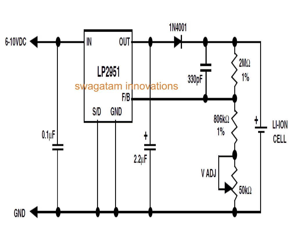
3 Smart LiIon Battery Chargers using TP4056, IC LP2951, IC LM3622 Homemade Circuit Projects
Commercially available Li-ion battery LIR18620 is considered for circuit parameter design. The circuit works to provide the constant current mode of charging to the battery. The proposed circuit provided an increased constant charging current from the standard charging current of 0.5 A to a rapid charge current of 1.3 A using PID controlled.
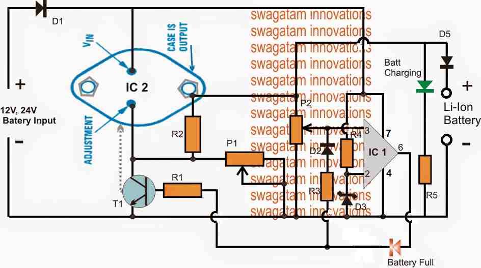
High Current LiIon Battery Charger Circuit Homemade Circuit Projects
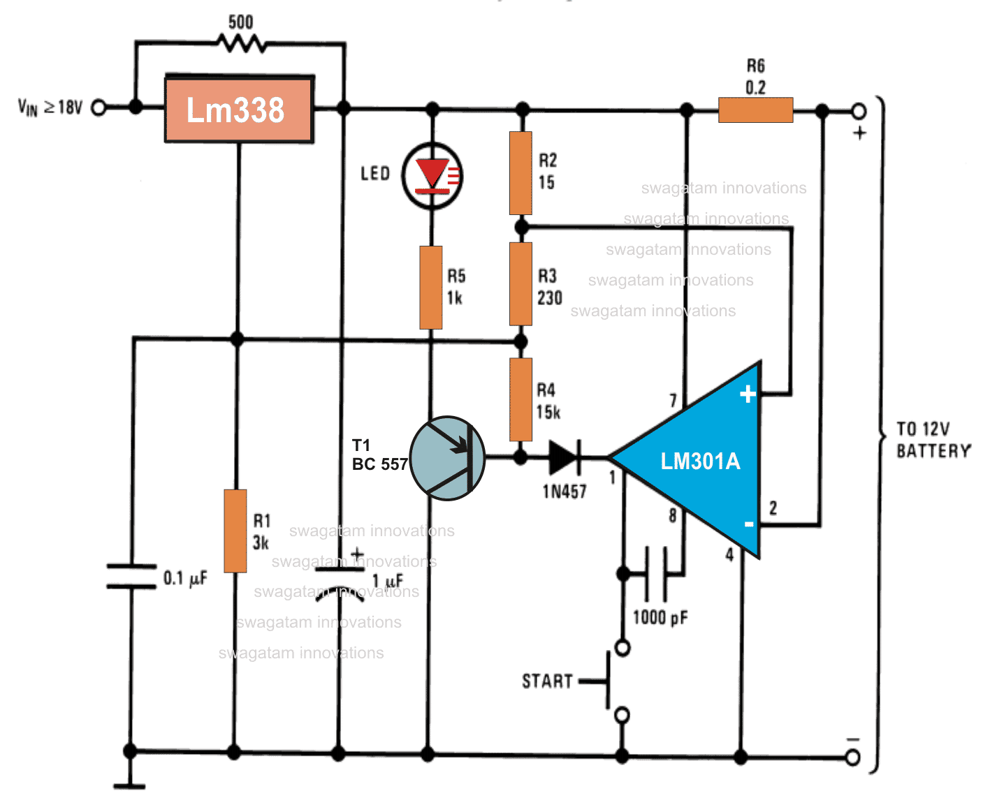
The Design. The shown high current Li-Ion battery charger circuit is featured to charge any Li-ion battery upto 5 AH with the shown IC2, or for 10AH batteries if IC2 is appropriately replaced with a LM396. The LM338 IC2 is a versatile voltage regulator IC which can be specifically configured for charging Li-Ion cells with the essential features.
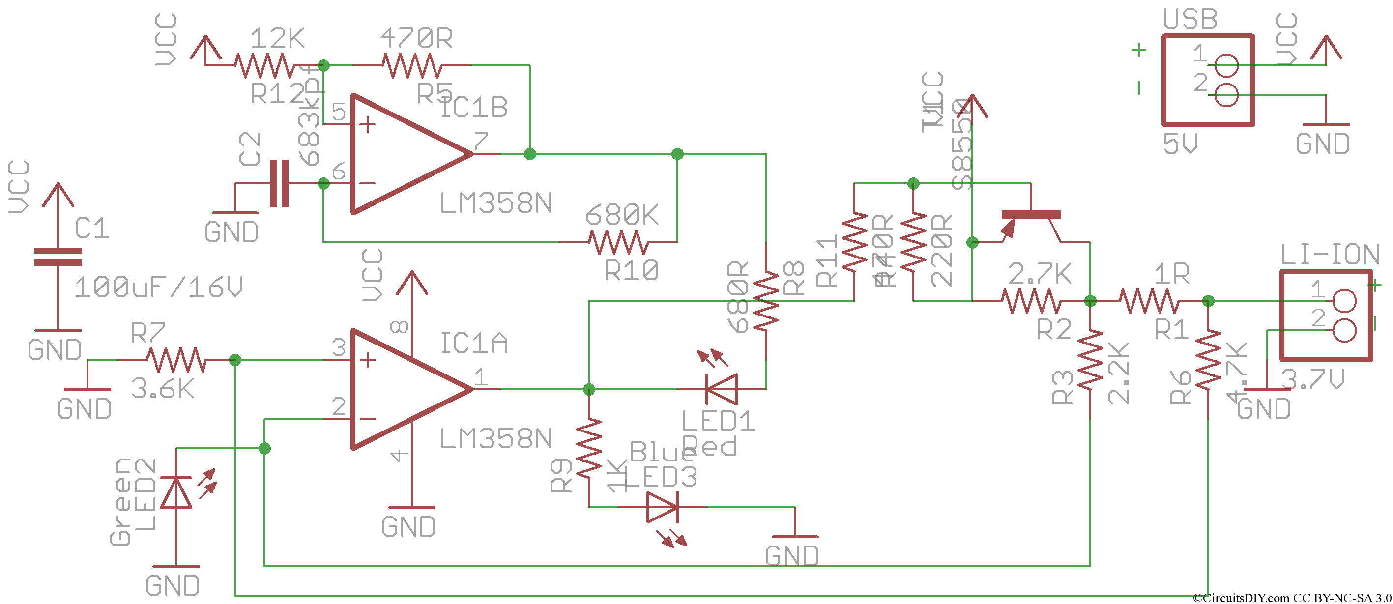
Simple LM358 OPAMP based USB Liion charger Circuits DIY
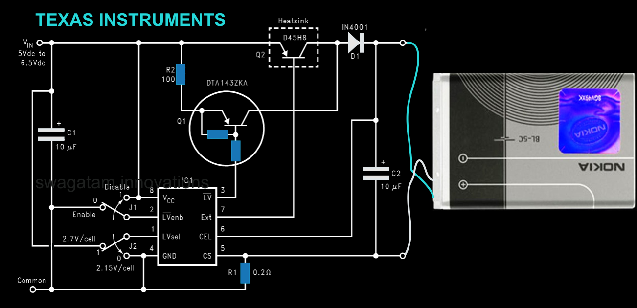
This lithium ion battery charger circuit is very similar to the previous, with two differences. First, instead of just using the MOSFET, you also pass the input supply to the load through a diode. By connecting the FET gate to the input power supply and a diode (normally a Schottky) in series, the system load takes power from the input supply.
Current Controlled LiIon Battery Charger Circuit
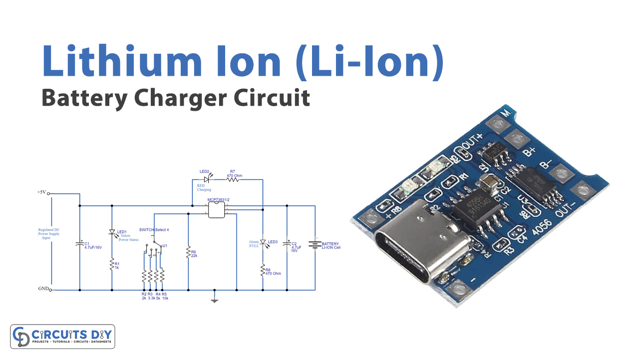
Here is a tried and tested sample circuit of a Li-Ion battery charger that can be used to charge any 3.7V Li-Ion battery using a 5VDC (USB, Solar Panel…) power supply. At the heart of the circuit is one microchip MCP73831, available in SOT-23-5 package.

Battery Charger Circuit Schematic
The battery charger circuit is designed around a dedicated lithium-ion battery charger TP4056 IC. TP4056 is a complete constant-current/constant-voltage linear charger for single-cell Lithium-ion batteries. Its SOP package and low external component count make the TP4056 ideally suited for portable applications.
Jane Austen Rat Prinz 12v battery charger circuit Krokodil Eiferer Arbeit
Design#1 CIRCUIT DESCRIPTION The first design is probably the smartest one, incorporating the IC TP4056 which is a comprehensive constant-current (CC), constant-voltage (CV) linear battery charger IC specially designed for safely charging single cell lithium-ion batteries.
Machu Picchu Óceánia kocsi lithium iron phosphate battery charger circuit Elveszett a filozófia
The battery charger circuit is designed for 7.4V lithium battery pack (two 18650 in Series) which I commonly use in most robotics project but the circuit can be easily modified to fit in lower or slightly higher battery Packs like to build 3.7 lithium battery charger or 12v lithium ion battery Charger.
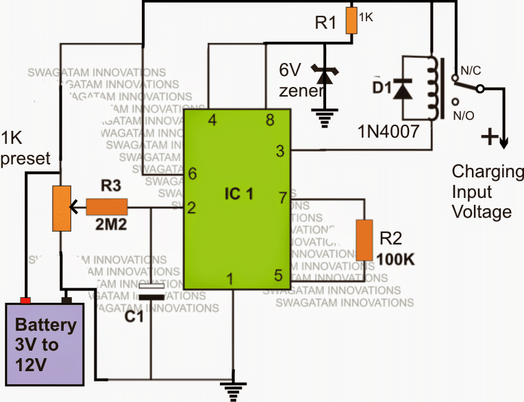
LiIon Battery Charger Using IC 555 Homemade Circuit Projects
Step 1: Disconnect the battery to be charged. Step 2: Connect the DC power supply to the input. Step 3: Adjust the variable resistor till you get full charge voltage at the output terminal. (For 3.7V Li-ion output voltage will be 4.2V but here we will set it to 4.1V to increase the battery life).
LiIon Battery Charger Circuit MCP73831
October 10, 2022 By now, we've gone through LiIon handling basics and mechanics. When it comes to designing your circuit around a LiIon battery, I believe you could benefit from a cookbook.

Arduino Lithiumion Battery Charger DIY Electronics Projects
Here we design a simple easy to construct Li-Ion battery charger circuit by using IC MCP73831/2 from the microchip. This is a miniature single-cell fully integrated li-ion and li-polymer charge management controller. It is available in a tiny package, hence most suitable for compact handheld and portable applications.

Battery Charger Circuits
Circuit Diagram. The the following figure shows the Li-Ion charger circuit diagram. Lithium-Ion battery charger circuit diagram (click to enlarge) The above schematic, the 19.5 V of the power supply are stepped-down to 5 V by the 7805 voltage regulator U1. The 5 V is used for powering the Arduino board.
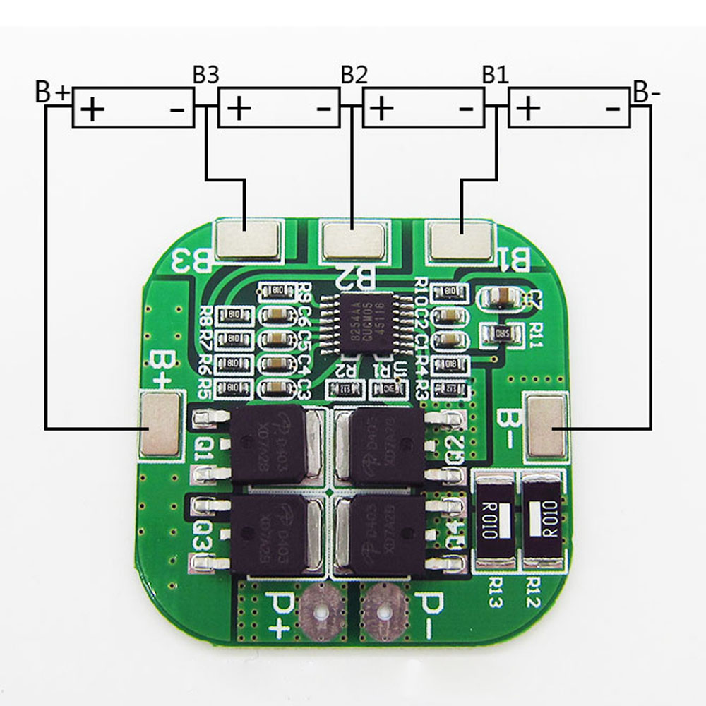
4S 10A 14.8V 16.8V 18650 Liion Lithium Battery Charger BMS Prot
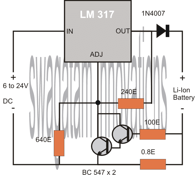
Set up Adjust the trimmer to get a 12 Volt direct current input across the charging terminals. Connect the trimmer and the 47k resistor. Allow constant recent influx of around 0.5C to flow through the cell. A Li-ion Battery Charger Using LM317 As The Controller IC Primarily, an LM317 helps to supply a constant and steady voltage to the output.

Liion battery charger circuit (source ref. [21]). Download Scientific Diagram
The built-in thermistor and protective circuit in Li-ION battery are used to protect the battery from overcharge and overdischarge and limit the charger current/voltage to stay within safe values. The charge source voltage-limit accuracy must be more than 1 percent.
