
Gate Valves Introduction, Types, Applicable Codes and Standards
The gate valve symbol used in piping and instrumentation diagrams (P&ID) is a modification of the valve symbol, which is the gate valve symbol without the vertical line between the triangles. The three isometric symbols in the diagram indicate symbols for butt-welding end connections, flanged ends, and socket ends connections.
Types Of Gate Valve And Parts Engineering Discoveries
gate valve, also known as a sluice valve, is a valve that opens by lifting a barrier (gate) out of the path of the . Gate valves require very little space along the pipe axis and hardly restrict the flow of fluid when the gate is fully opened.
Technical drawing of a Rising Stem Gate Valve OSandY
Gate valves (also known as knife valves or slide valves) are linear motion valves in which a flat closure element slides into the flow stream to provide shut-off. They are one of the most common valves used. Find Gate Valves by Specification or See our Directory of Suppliers Gate valve. Video Credit: CTE Skills.com / CC BY-SA 4.0
Ball Valves vs Gate Valves The Home Depot
Understanding gate valve diagram s: A Comprehensive Guide Gate valves are essential components in various industrial applications, allowing for the control and regulation of fluid flow. To fully comprehend the functioning of gate valves, it is crucial to understand their diagrams.
gate valve diagram with parts Gate instrumentationtools disadvantages
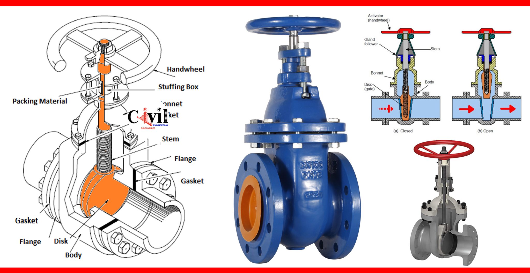
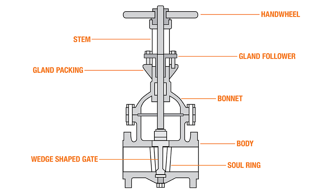
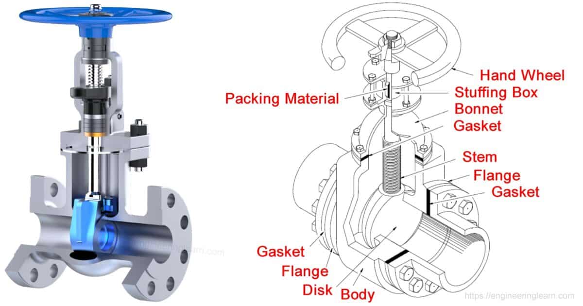
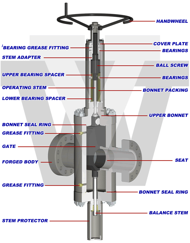
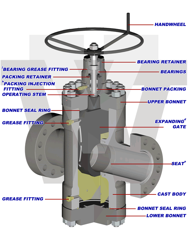
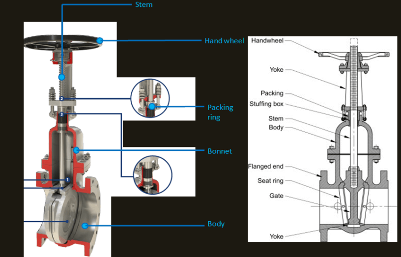
When you look at a gate valve diagram or a gate valve parts diagram, you can see the major components that make up this powerhouse: the body, the bonnet, the stem, the gate or disc, and the seat rings. At the heart of the valve, the valve body houses the valve's internals and is typically made of ductile iron, cast iron, or stainless steel.

What is an Industrial Gate Valve? MSEC
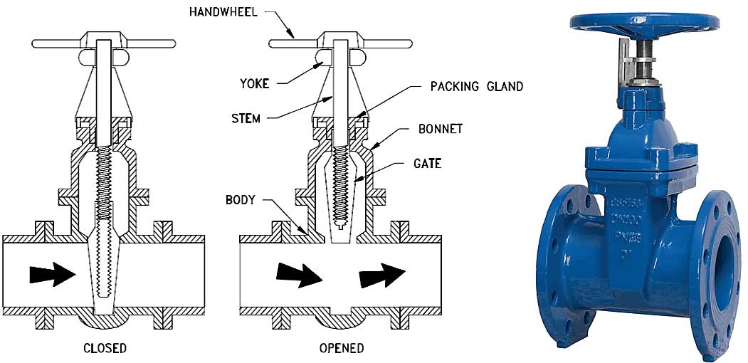
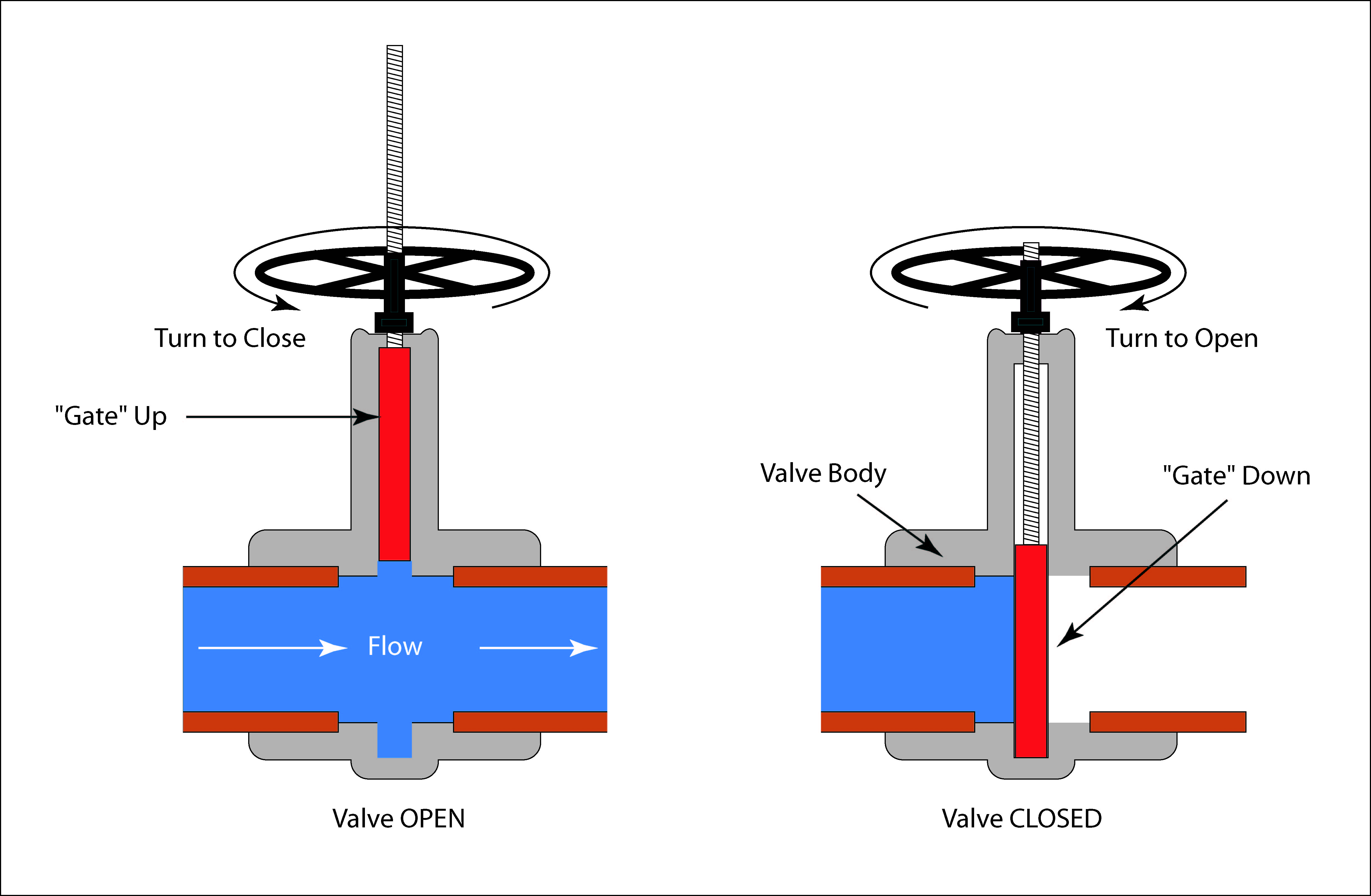
A gate valve is a linear motion valve used to start or stop fluid flow; however, it does not regulate or throttle flow. The name gate is derived from the appearance of the disk in the flow stream. Figure illustrates a gate valve. The disk of a gate valve is completely removed from the flow stream when the valve is fully open.
FM4 SERIES GATE VALVES Valveworks USA
A gate valve can be defined as a type of valve that uses a gate or wedge-type disk, which moves perpendicular to flow to start or stop the fluid flow in piping. It is the most common type of that used in any process plant. It is a linear motion valve used to start or stop fluid flow.
What is Gate Valve ? Gate Valve Parts Disadvantages of Gate Valve
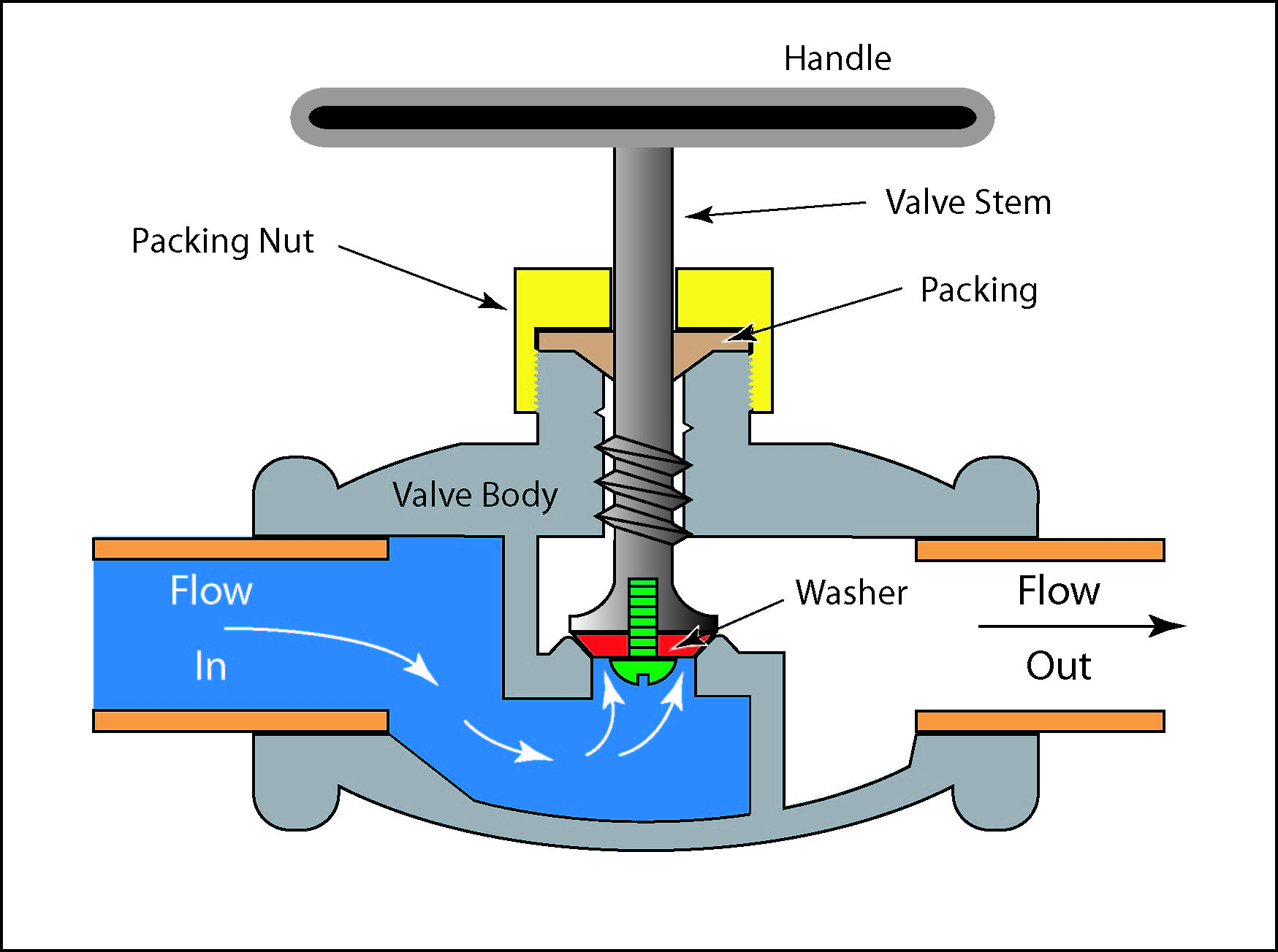
Gate valve bodies can have many different process connections that can include: flanged, threaded, and welded parts. The valve body has a recess into which the gate slides. The sides of these recesses are called the seat. The gate sits precisely against these faces when it is closed to effectively seal the valve.
FM4 SERIES GATE VALVES Valveworks USA
Functioning Principle The body, seat, gate, stem, bonnet, and actuator are the essential components of a gate valve. The primary mechanism of operation is straightforward. Common gate valves are activated by a threaded stem that connects the actuator, e.g., handwheel or motor, to the gate.
GATE VALVES Types Bertrem Products Inc.
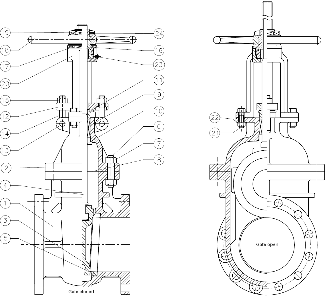
Stem Gate valves can have a rising or nonrising stem design. Rising stems are attached directly to the gate and provide a visual indicator of the valve position. Nonrising stems are generally threaded into the upper part of the gate and have a pointer threaded onto the top to indicate position.
Type of Gate Valves The piping talk
A gate valve is a wall that has dual flow directions. It is not subject to the flow direction of the medium. Therefore, it is suitable for use in the pipeline where the medium may change the flow direction. Disadvantage of Gate Valve: The following disadvantages or demerits of Gate Valve is: We cannot use a gate valve for controlling the flow.
gate valve diagram construction Parts of gate valve plus top 5 functions hpd team
Gate valves are called 'full-flow' valves; there's a direct unobstructed path for flow right through the middle of the valve. A wedge-shaped brass gate is lowered into a machined slot to close the valve. They should either be completely open or completely closed.
Valves Manual Valves Globe Valves CTG Technical Blog
A Gate valve is a linear-motion manual valve that has a vertical rectangular or circular disc that slides across an opening to stop the flow that acts as a "gate".

What is Gate Valves Diagram , Working , Advantages , Applications
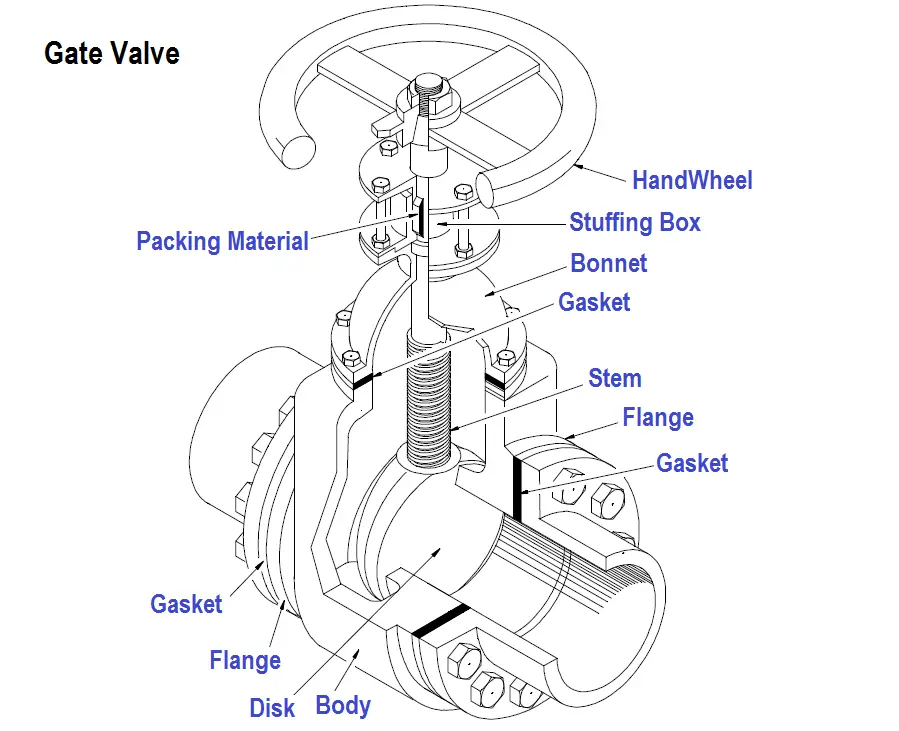
Gate valve diagram & parts A gate valve has seven main parts, which can be seen in Figure 3, which are: handwheel (A), stem (B), gasket (C), bonnet (D), valve body (E), flange (F), and gate (G). A flanged gate valve or threaded gate valve is the most common connection type to connect the valve to an application.
Valves Manual Valves Gate and Butterfly Valves CTG Cleaning Technologies, Inc.
Apply 3-in-one or penetrating oil to the gate valve. Wipe the excess oil with a rag and ensure that the oil reaches the valve's threads. Tap the valve handle with a hammer to check if the valve changes position from open to closed. Attach an adjustable wrench or channel lock on the valve handle.
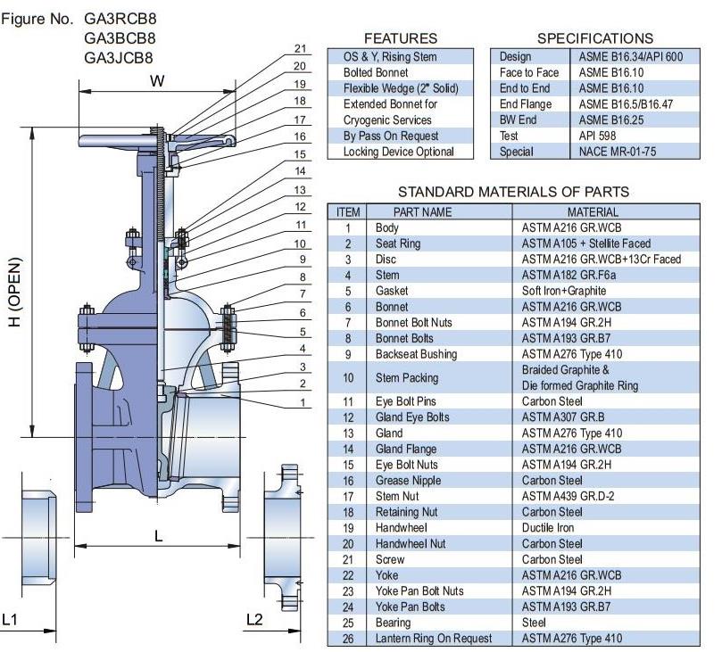
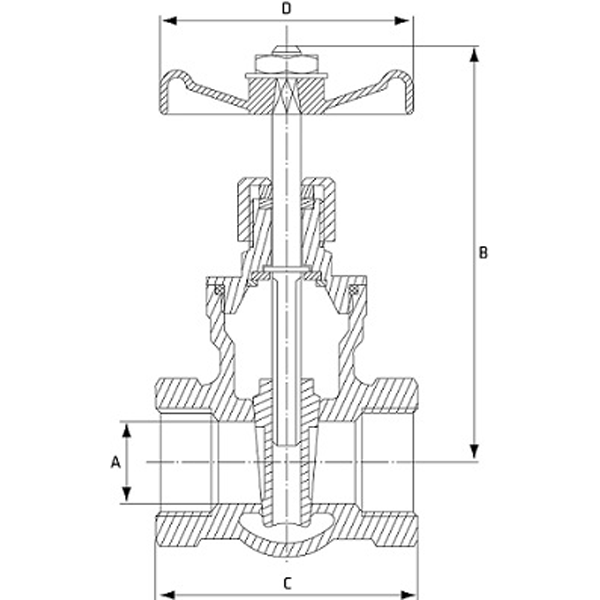
Cast Steel Gate Valve, Drawings, Dimensions & Weight Relia Valve
Gate Valve Components. The main parts of the gate valve include body, gate, bonnet, stem, packing gland and yoke. Gate valve construction; Credit: CC BY-SA 4.0. The body of a gate valve holds all of the operational parts of the valve. It is connected to the system with one of the mounting options below.
