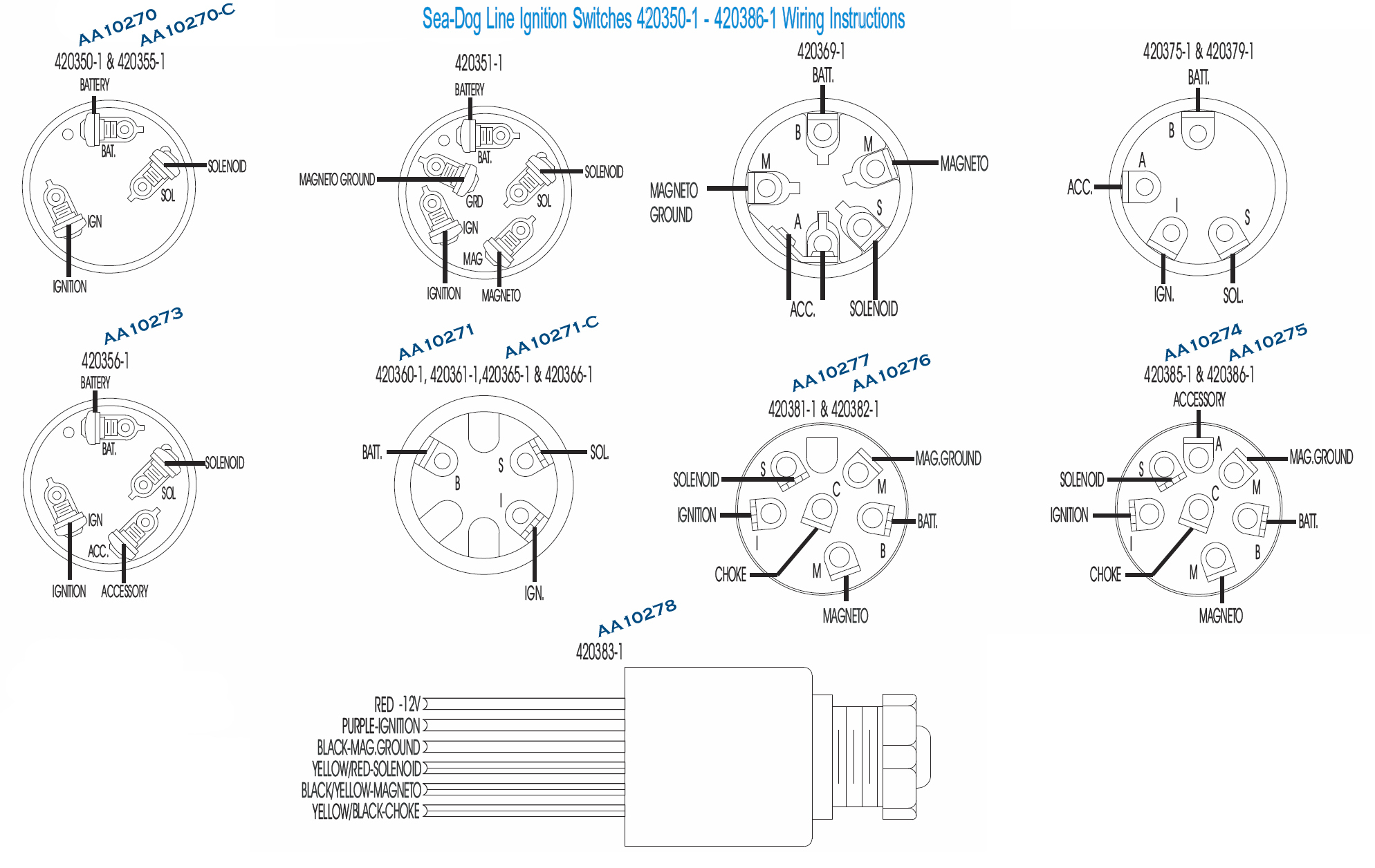
Ignition Switch Circuit Diagram
1. Power Tests Check & test wires and devices with regard to power inside the box you usually are working in to stop electric shock just before working on them. Sometimes, even when you shut off power, some cabling may be connected to another circuit & hence may still pose a danger of electric surprise. 2. Uncoil Cable
Lawn Mower 5 Prong Ignition Switch Wiring Diagram Database
Step 1: Obtain a circuit diagram Step 2: Locate all components that need wiring Step 3: Connect the switch to ground Step 4: Connect the switch to the Solenoid Step 5: Wire the magneto to the switch Step 6: Provide voltage by connecting the battery Step 7: Connect the accessories/ lights Step 8: Screw the switch in place
7 Terminal Ignition Switch Wiring Diagram Cadician's Blog
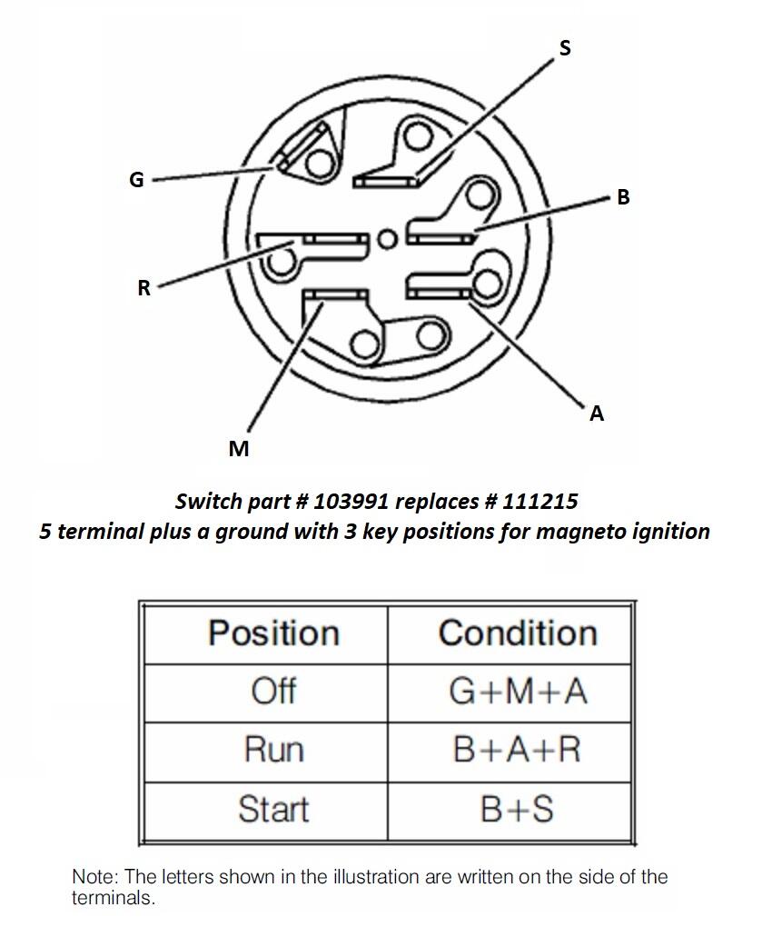
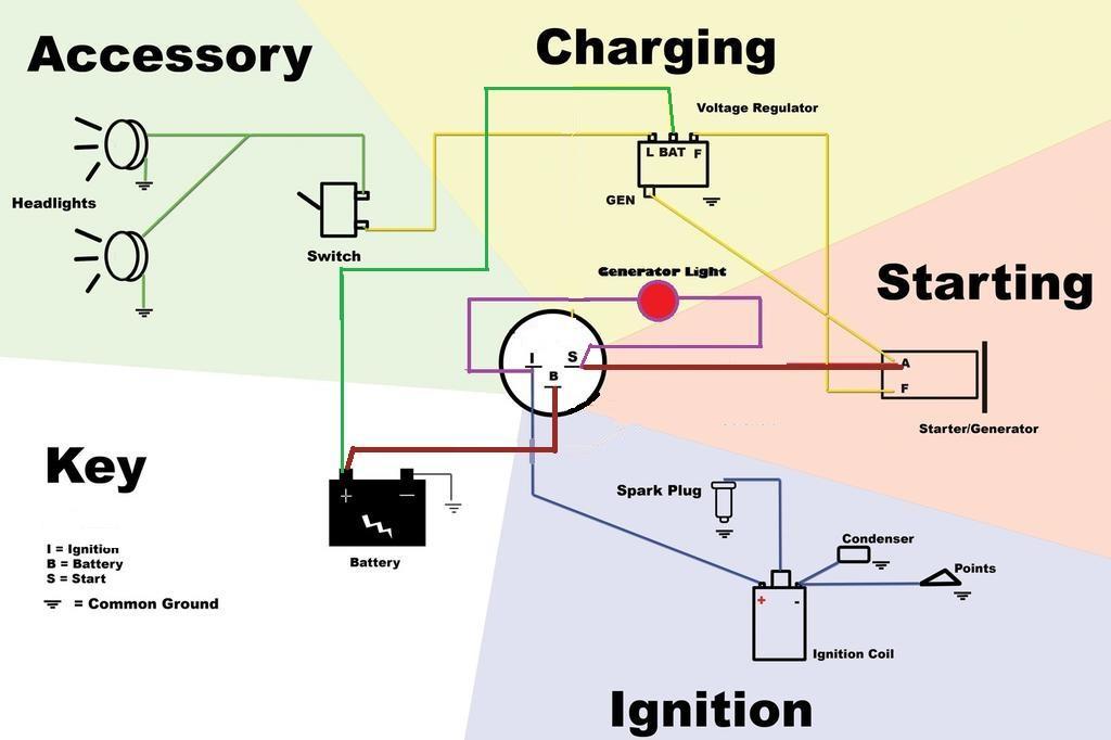
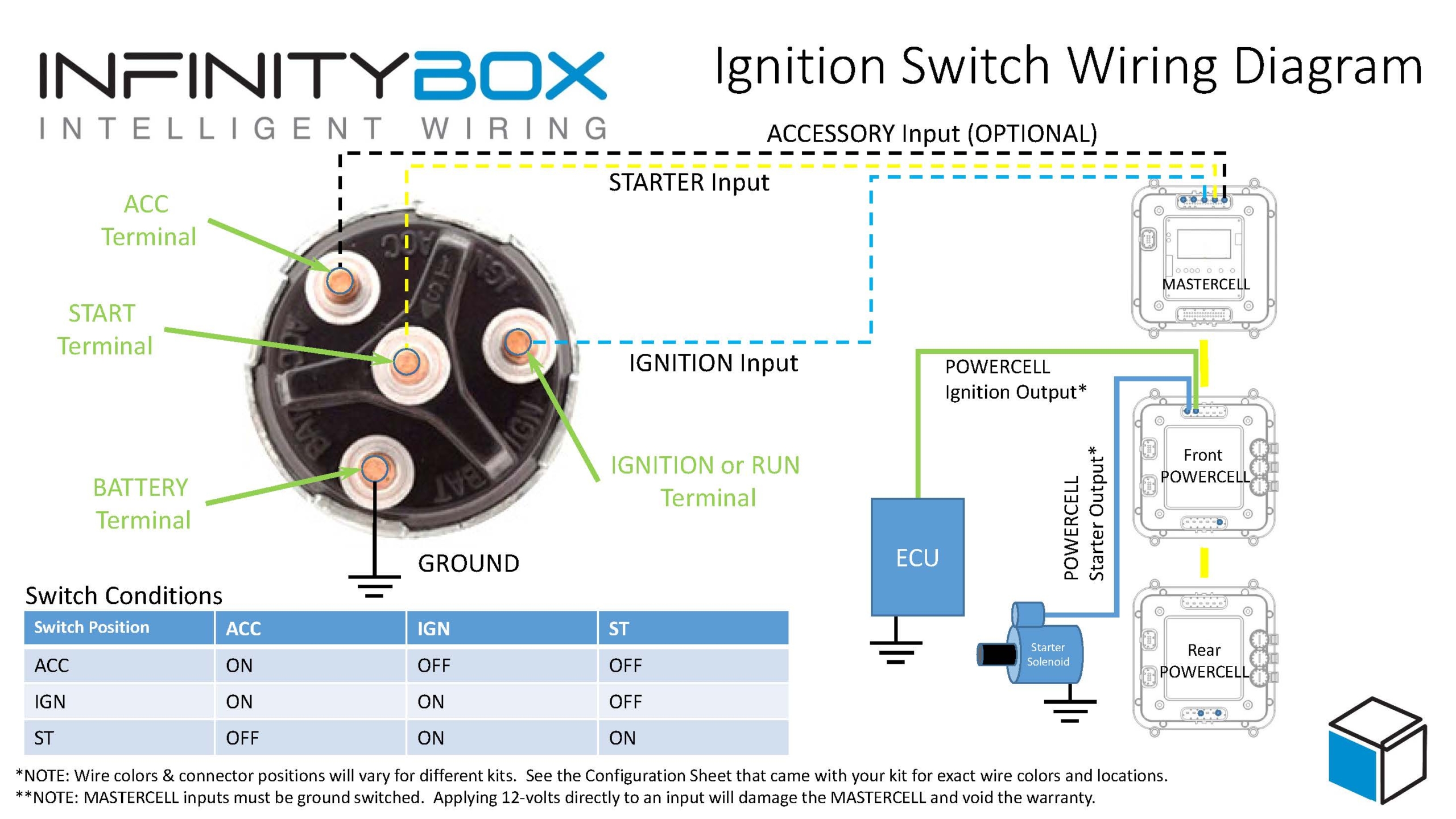
A1 Connecteded to B in the ON & Start position. L & Y are typically the light switch. IF the tractor engine has an AC charge coil for headlights, it probably goes to Y and L goes to the lights. S Starter solenoid. Connects to B in the START position only. M is USUALLY the kill wire to the ignition coil and grounded to G when the key is off.
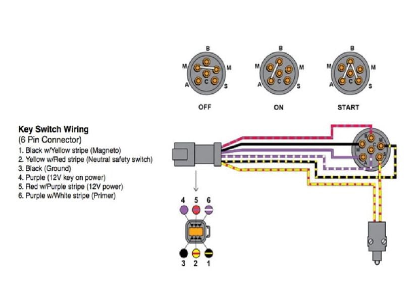
Evinrude Etec Ignition Switch Wiring Diagram
Step 1: Gather the Necessary Tools and Materials Before starting the wiring process, make sure you have all the necessary tools and materials. This may include a 7 prong ignition switch, wire cutters, wire strippers, electrical tape, crimping tool, and a wiring diagram. Step 2: Familiarize Yourself with the Wiring Diagram
Share 59+ images land rover defender ignition switch replacement In
The 7 terminal ignition switch wiring diagram is a basic guide that explains the wiring setup of the switch. It will show the connections between the various components of the ignition switch, such as the ignition coil, starter solenoid, starter motor, and other components.
7 Terminal Ignition Switch Wiring Diagram Collection Wiring Diagram
There are typically seven terminals on an ignition switch, each serving a specific function. These terminals include battery power, ignition switch power, start solenoid, accessory power, ignition coil, and instrument panel lights.
5 Prong Ignition Switch Wiring Diagram
To ignition system To starter motor solenoid To accessories e.g. radio, lights, cigar sockets etc. IGNITION SWITCH Brass terminals on switch Wiring Diagram For 4 Position Universal Ignition Switch Product Code P00940
7 Terminal Ignition Switch Wiring Diagram Drivenheisenberg
1. Prepare Vehicle Before you start any at-home job on your vehicle, you should prepare everything ahead of time. It's important to gather all of your tools and equipment in advance. Otherwise, you are going to be running around getting parts and tools while you are in the middle of the job.
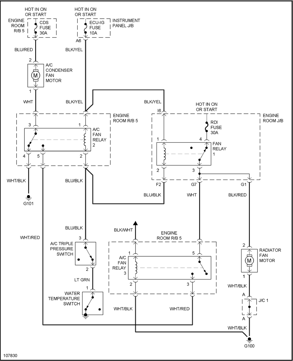
Toyota Corolla Questions My Engine Fan Turns On When I Turn The 7
5 Pole Ignition Switch Wiring Diagram: Step 1 Park the vehicle and start by opening your hood, check the negative terminal of the battery, and detach the terminal locking nuts holding it to the negative post on the battery.
7 Terminal Ignition Switch Wiring Diagram Cadician's Blog
A 7 terminal ignition switch wiring diagram is an essential tool in maintaining the safety and performance of your machine. This diagram shows the electrical connections between the battery, starter solenoid, keyswitch, and other components within the circuit. The importance of having a clear wiring diagram cannot be overstated.
7 Terminal Ignition Switch Wiring Diagram
The diagram allows you to connect wires from different parts of the vehicle - such as the starter motor, an alternator, or the distributor - with the appropriate pin on the switch itself. The wiring diagram shows which wire goes to which pin on the actual switch.
The Wiring Diagram Of An Ignition Switch Explained Moo Wiring
1 offer from $9.90 New Starter Compatible with Briggs & Stratton 1972-2002 7HP-18HP Engines 390838, 391423, 392749, 394805, 491766, 497594, 497595, 693054, SBS0001, 41022003, 41022003R, 41022052
7 Terminal Ignition Switch Wiring Diagram Drivenheisenberg
July 30, 2023 1 min read If you're looking to replace your existing lawn mower ignition switch, it's important to know the wiring diagram for various types of ignition switches. This article provides detailed instructions and diagrams for wiring 7 prong ignition switches, including safety concerns and tips on how to get the job done.
wiring diagram 7 Terminal Ignition Switch Wiring Diagram
Bob testing an ignition switch is pretty simple, there will be one power input and the other terminals will all get power at different points of the ignition being turned. if you can send a picture of the bottom of the switch there are numbers near each terminal that tell you a circuit.

7 Terminal Ignition Switch Wiring Diagram Wiring Diagram Schematic
However, if you can't find the right switch, give our customer service representatives a call. We're happy to assist in any way! If you do not see the Ignition Switch you need, please complete the Lawn Mower Parts Request Form and we will be happy to assist you. Oregon 33-375. Oregon 33-389. Oregon 33-397.
7 terminal ignition switch wiring diagram
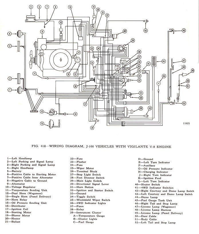
Location: Western NC. #1. Posted June 12, 2018 (edited) I have a few basic electrical system diagrams that are helpful in understanding how the wiring system works. They are not specific to any particular tractor and do not include safety switches. All use the 5 post ignition switches 103-991 for Magneto and 103-990 for Battery Ignition.
