
Battery Isolator Wiring Schematic Free Wiring Diagram
The Diode Battery Isolator. The diode type battery isolator uses semiconductor diodes to split the current from the alternator or generator and charge 2 or more batteries at the same time. One battery is used to start the engine and the other is used to run the accessories. The load on the accessory battery does not drain the starting battery.
Dual Battery Isolator Wiring Diagram For Integrator1 Jpg In System
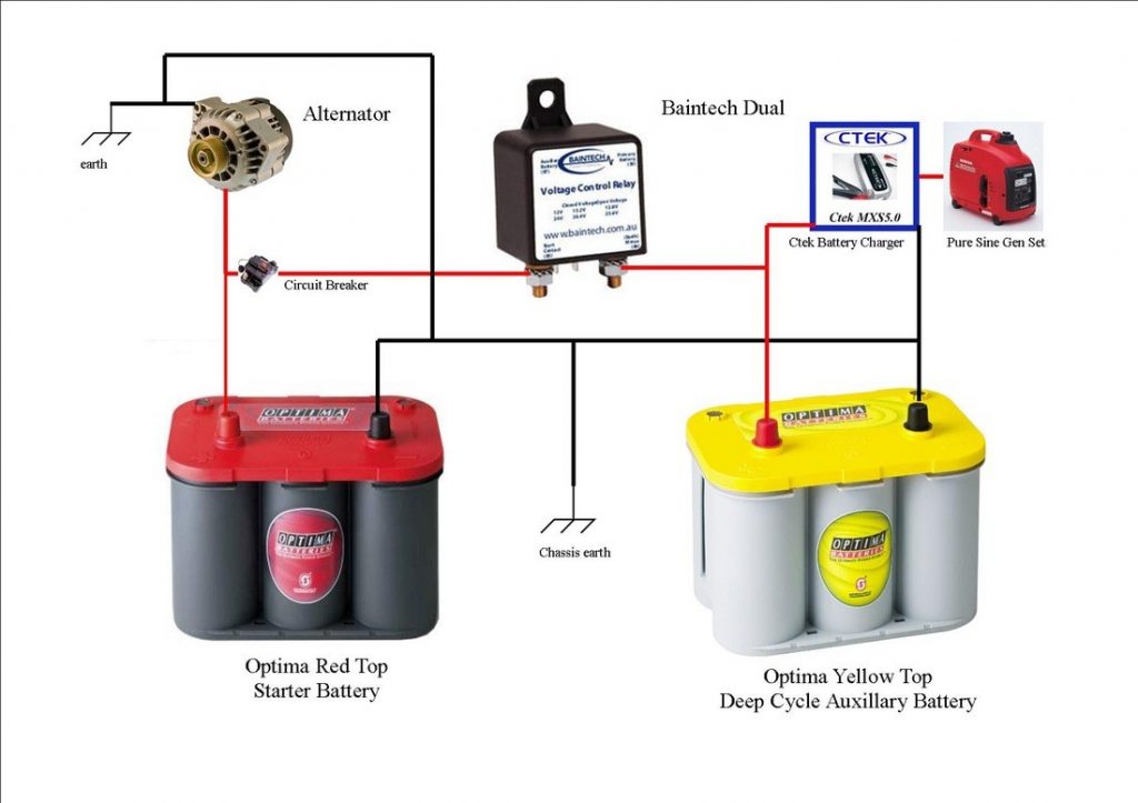
The battery isolator allows two batteries to be charged at the same time. When the engine is started and the start battery reaches 13.7v, the isolator engages, allowing two battery banks (start and house) to be charged simultaneously. When the voltage drops below 12.8v (eg the engine is stopped), the isolator disengages, separating both batteries.

Lets talk dual battery isolators Toyota FJ Cruiser Forum
An overview of how to wire a Stinger isolator to run dual batteries in a truck, van, or car. The isolator keeps the main battery from going dead. 200 amp St.

Dual Battery Isolator Wiring Diagram Wiring Harness Diagram
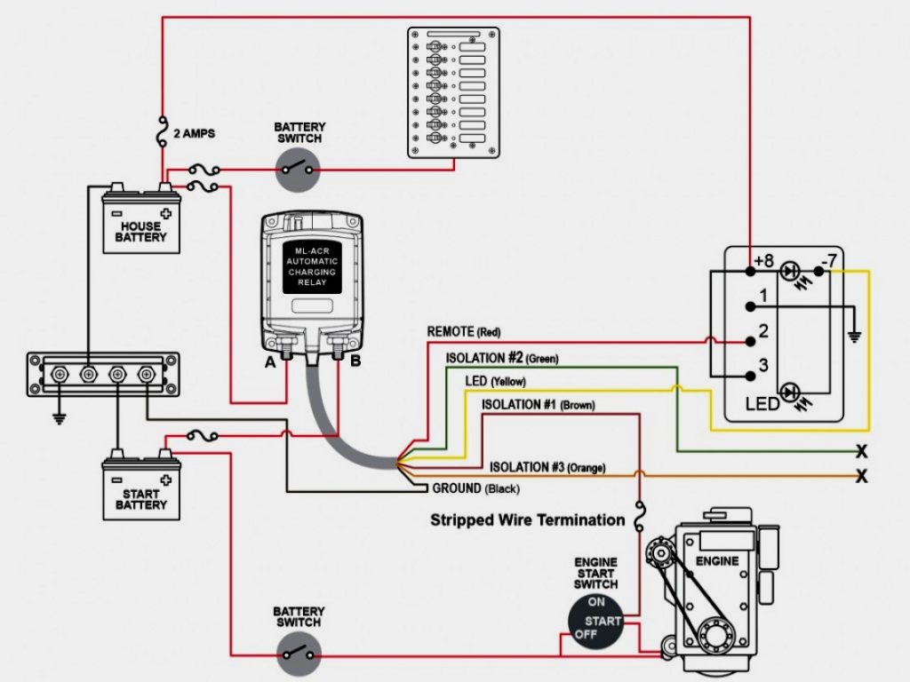
Dual Battery Jump-Start. Customers have been a fan of our 'Ultimate Dual Battery setup' for years now as it enables all the benefits of charging through a BCDC and the safety and convenience of an added jumpstart feature. Addionally, Solar could be added on BCDC1225 (-LV) and BCDC1240 (LV) installations with the 'BCDC with 12V and Solar Inputs.
Battery Isolator Switch Wiring Diagram
Wish List. We go through options for a dual battery kit and what to look out for.
12v Battery Isolator Wiring Diagram wiring is life
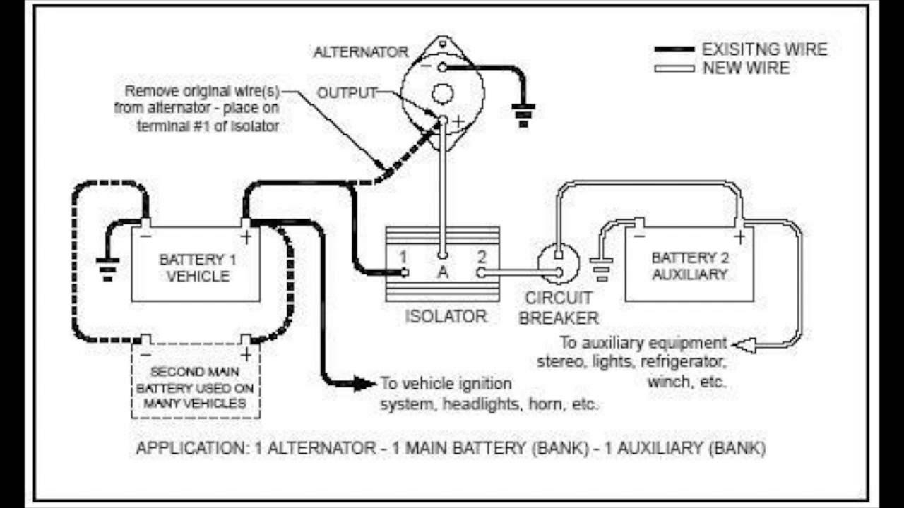
Wiring is accomplished by: Connect a cable from the positive terminal of the primary battery by removing one of the nuts of the threaded studs on the back of the isolator. Apply cable, replace the nut and tighten securely. Then connect a second cable from the isolator's remaining threaded stud to the positive terminal of the second battery.
Trailer Battery Wiring Diagram Wiring Diagram
Connect the thin (-) black. 4 earth wire from the VSR to the vehicle chassis or the starter battery's negative. Ensure your installation. 10 is correct then connect the (+) positive lead to the start battery. Connect the (+) positive. 3 wire coming from the circuit breaker to the terminal on the VSR marked RED. Mount the circuit breaker under.
Sure Power Battery Isolator Wiring Diagram Cadician's Blog
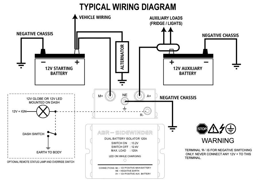
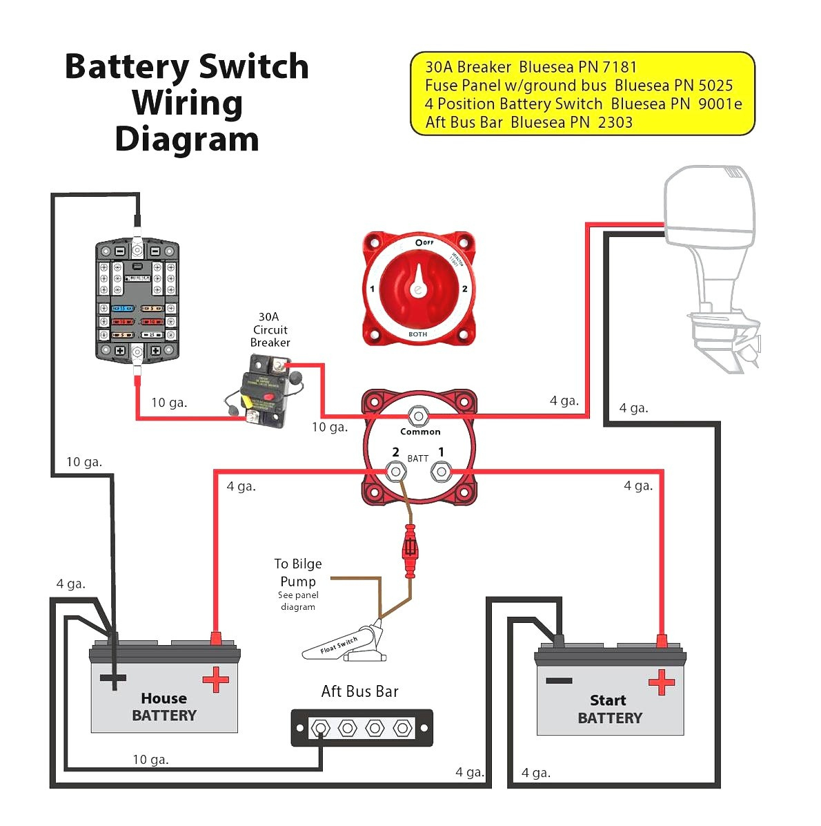
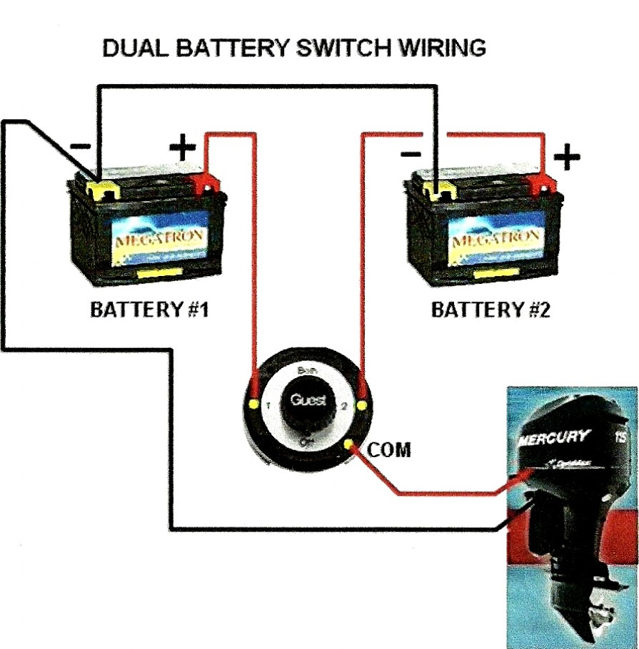
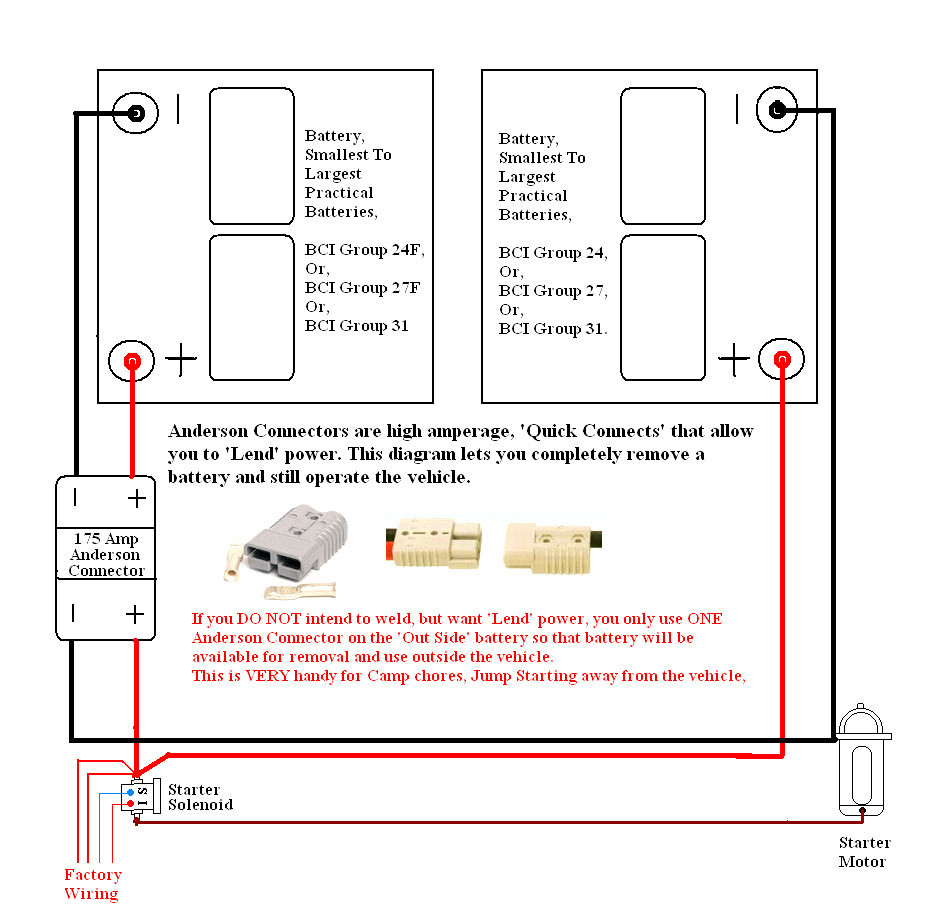
A dual battery isolator wiring diagram is a visual representation of how each component of the system is connected. The diagram will typically show the battery, the isolator, and the connections between them. The diagram will also show the current flow from the batteries to the isolator and from the isolator to the electrical accessories.

17+ best images about 12 volt electrical, wiring, charging
Connect the isolator's 'Earth' wire (small black wire with ring terminal) to a suitable chassis bolt or screw, ensure the ring terminal will make a good electrical connection by removing any paint. Reconnect the starting (main) battery's negative cable (Earth), the isolator should now flash the red 'power' LED.

How to wire dual batteries/isolator/battery selector switch Texas 4x4
Awesome Prices & High Quality Here On Temu. New Users Enjoy Free Shipping & Free Return. Come and check All Categories at a surprisingly low price, you'd never want to miss it.

Dual Battery Isolator Circuit Diagram
Shop Toolstation Cable And Other Power Electrical Products At Toolstation. Find Great Deals Online On A Wide Range Of Electricals.
12v Dual Battery Wiring
Step 2: Attach the Wires to the Isolator. Strip the end of the red positive cable and cap the end with a ring terminal. Then similarly, put a blue insulated ring terminal on the end of the black ground wire on the isolator. Be sure to crimp it in place. There are bolts on the underside of the isolator. Punch out holes of the wires beneath the.
Dual Battery Isolator Wiring Diagram Wiring Harness Diagram
Step by step Battery Isolator install (12V 140 Amp Dual Battery Isolator by KeyLine Chargers - Voltage Sensitive Relay (VSR) Pro Dual Battery Kit). This isol.
Dual Battery Isolator Wiring Diagram Cadician's Blog
Ultimate dual battery setup for winching. Customers have been a fan of our Ultimate Dual Battery setup for years now as it enables all the benefits of charging through a BCDC and the safety and convenience of an added jumpstart feature. With most 4WD enthusiasts, especially those tackling the difficult tracks remotely tend to opt for a winch as.
Battery Isolator Wiring Diagram Sp Wiring Diagram Dual Battery
Wiring Diagram - 12V DUAL BATTERY SYSTEM WITH ISOLATOR. Looking For More Wiring Diagrams? Click me!

Famous Dual Battery Isolator Diagram Ideas
The wiring diagram for a boat dual battery system typically includes several key components. These include a battery switch, battery isolator, voltage-sensitive relay, and various fuse blocks and cables. Each component plays a vital role in ensuring the proper functioning of the dual battery system. The battery switch is an essential component.
